Page text
Page: 2 of 2
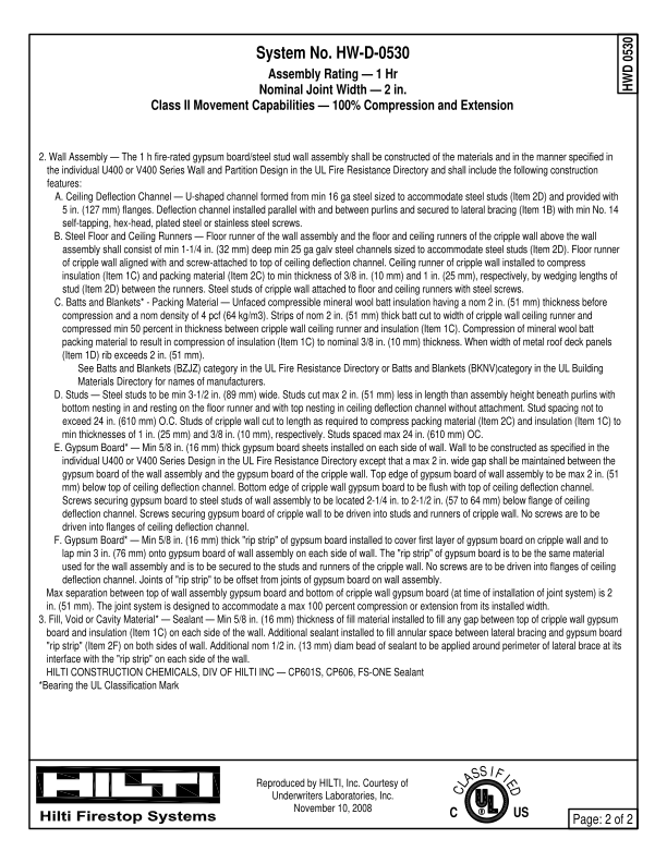
2. Wall Assembly — The 1 h fire-rated gypsum board/steel stud wall assembly shall be constructed of the materials and in the manner specified in
the individual U400 or V400 Series Wall and Partition Design in the UL Fire Resistance Directory and shall include the following construction
features:
A. Ceiling Deflection Channel — U-shaped channel formed from min 16 ga steel sized to accommodate steel studs (Item 2D) and provided with
5 in. (127 mm) flanges. Deflection channel installed parallel with and between purlins and secured to lateral bracing (Item 1B) with min No. 14
self-tapping, hex-head, plated steel or stainless steel screws.
B. Steel Floor and Ceiling Runners — Floor runner of the wall assembly and the floor and ceiling runners of the cripple wall above the wall
assembly shall consist of min 1-1/4 in. (32 mm) deep min 25 ga galv steel channels sized to accommodate steel studs (Item 2D). Floor runner
of cripple wall aligned with and screw-attached to top of ceiling deflection channel. Ceiling runner of cripple wall installed to compress
insulation (Item 1C) and packing material (Item 2C) to min thickness of 3/8 in. (10 mm) and 1 in. (25 mm), respectively, by wedging lengths of
stud (Item 2D) between the runners. Steel studs of cripple wall attached to floor and ceiling runners with steel screws.
C. Batts and Blankets* - Packing Material — Unfaced compressible mineral wool batt insulation having a nom 2 in. (51 mm) thickness before
compression and a nom density of 4 pcf (64 kg/m3). Strips of nom 2 in. (51 mm) thick batt cut to width of cripple wall ceiling runner and
compressed min 50 percent in thickness between cripple wall ceiling runner and insulation (Item 1C). Compression of mineral wool batt
packing material to result in compression of insulation (Item 1C) to nominal 3/8 in. (10 mm) thickness. When width of metal roof deck panels
(Item 1D) rib exceeds 2 in. (51 mm).
See Batts and Blankets (BZJZ) category in the UL Fire Resistance Directory or Batts and Blankets (BKNV)category in the UL Building
Materials Directory for names of manufacturers.
D. Studs — Steel studs to be min 3-1/2 in. (89 mm) wide. Studs cut max 2 in. (51 mm) less in length than assembly height beneath purlins with
bottom nesting in and resting on the floor runner and with top nesting in ceiling deflection channel without attachment. Stud spacing not to
exceed 24 in. (610 mm) O.C. Studs of cripple wall cut to length as required to compress packing material (Item 2C) and insulation (Item 1C) to
min thicknesses of 1 in. (25 mm) and 3/8 in. (10 mm), respectively. Studs spaced max 24 in. (610 mm) OC.
E. Gypsum Board* — Min 5/8 in. (16 mm) thick gypsum board sheets installed on each side of wall. Wall to be constructed as specified in the
individual U400 or V400 Series Design in the UL Fire Resistance Directory except that a max 2 in. wide gap shall be maintained between the
gypsum board of the wall assembly and the gypsum board of the cripple wall. Top edge of gypsum board of wall assembly to be max 2 in. (51
mm) below top of ceiling deflection channel. Bottom edge of cripple wall gypsum board to be flush with top of ceiling deflection channel.
Screws securing gypsum board to steel studs of wall assembly to be located 2-1/4 in. to 2-1/2 in. (57 to 64 mm) below flange of ceiling
deflection channel. Screws securing gypsum board of cripple wall to be driven into studs and runners of cripple wall. No screws are to be
driven into flanges of ceiling deflection channel.
F. Gypsum Board* — Min 5/8 in. (16 mm) thick "rip strip" of gypsum board installed to cover first layer of gypsum board on cripple wall and to
lap min 3 in. (76 mm) onto gypsum board of wall assembly on each side of wall. The "rip strip" of gypsum board is to be the same material
used for the wall assembly and is to be secured to the studs and runners of the cripple wall. No screws are to be driven into flanges of ceiling
deflection channel. Joints of "rip strip" to be offset from joints of gypsum board on wall assembly.
Max separation between top of wall assembly gypsum board and bottom of cripple wall gypsum board (at time of installation of joint system) is 2
in. (51 mm). The joint system is designed to accommodate a max 100 percent compression or extension from its installed width.
3. Fill, Void or Cavity Material* — Sealant — Min 5/8 in. (16 mm) thickness of fill material installed to fill any gap between top of cripple wall gypsum
board and insulation (Item 1C) on each side of the wall. Additional sealant installed to fill annular space between lateral bracing and gypsum board
"rip strip" (Item 2F) on both sides of wall. Additional nom 1/2 in. (13 mm) diam bead of sealant to be applied around perimeter of lateral brace at its
interface with the "rip strip" on each side of the wall.
HILTI CONSTRUCTION CHEMICALS, DIV OF HILTI INC — CP601S, CP606, FS-ONE Sealant
*Bearing the UL Classification Mark
C
US
C
L
A
S
S
I
F
I
E
D
System No. HW-D-0530
HWD 0530
Reproduced by HILTI, Inc. Courtesy of
Underwriters Laboratories, Inc.
November 10, 2008
Assembly Rating — 1 Hr
Nominal Joint Width — 2 in.
Class II Movement Capabilities — 100% Compression and Extension