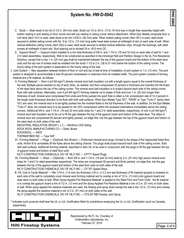
Page text
Page: 4 of 4
Hilti Firestop Systems
HWD 0042
Reproduced by HILTI, Inc. Courtesy of
Underwriters Laboratories, Inc.
February 07, 2019
System No. HW-D-0042
C.Studs — Steel studs to be min 2-1/2 in. (64 mm) wide. Studs cut 1/2 to 3/4 in. (13 to 19 mm) less in length than assembly height with
bottom nesting in and resting on floor runner and with top nesting in ceiling runner without attachment. When Epic Metals composite floor or
roof deck (Item 1A1) is used, steel studs to be min 3-5/8 in. (92 mm) wide. When slotted ceiling runner (Item 2A1) is used, steel studs
secured to slotted ceiling runner with No. 8 by 1/2 in. (13 mm) long wafer head steel screws at midheight of slot on each side of wall. When
vertical deflection ceiling runner (Item 2A2) is used, steel studs secured to slotted vertical deflection clips, through the bushings, with steel
screws at midheight of each slot. Stud spacing not to exceed 24 in. (610 mm) OC.
D.Gypsum Board* — Gypsum board installed to a min total thickness of 5/8 in. and 1-1/4 in. (16 and 32 mm) on each side of wall for 1 and
2 hr rated assemblies, respectively. Wall to be constructed as specified in the individual Wall and Partition Design in the UL Fire Resistance
Directory, except that a max 1 in. (25 mm) gap shall be maintained between the top of the gypsum board and the bottom of the steel deck
units and the top row of screws shall be installed into the studs 1-1/2 to 2 in. (38 to 51 mm) below the bottom of the ceiling runner. The
hourly rating of the joint system is dependent on the hourly rating of the wall.
3. Joint System — Max separation between bottom of floor or roof and top of wall at time of installation of joint system is 1 in. (13 mm). The joint
system is designed to accommodate a max 50 percent compression or extension from its installed width. The joint system consists of forming
material and a fill material, as follows:
A. Forming Material* — Nom 4 pcf (64 kg/m3) density mineral wool batt insulation cut with a length approx equal to the overall thickness of
the wall. Multiple pieces stacked on top of each other, as needed, and then compressed 25 percent in thickness and inserted into the flutes
of the steel deck above the top of the ceiling runner. The mineral wool batt insulation is to project beyond each side of the ceiling runner,
flush with wall surfaces. Alternately, nom 4 pcf (64 kg/m3) forming material cut to shape of flute and nom 1 in. (25 mm) longer than
thickness of wall; mineral wool compressed from ends and firmly packed into each flute to attain a min compression rate of 14.3 percent in
the length (wall thickness) direction to be flush with both wall surfaces. When Epic Metals Type "EC", "ER2R" or Type "Toris C" decks (Item
1A1) are used, the mineral wool is to be tightly packed into the inverted flutes to the full thickness of the wall. In addition, for the Epic Metals
"Toris C" deck, the mineral wool is to be packed to min 25% compression within the recessed indentations immediately above the ceiling
runners. Additional 5/8 in. and 1-1/4 in. (16 and 32 mm) wide strips for 1 and 2 hr rated assemblies, respectively, of nom 4 pcf (64 kg/m3)
mineral wool batt insulation are to be cut to fill the gap between the top of the gypsum board and bottom of the steel deck. The strips of
mineral wool are compressed 50 percent and tightly packed, cut edge first, into the gap between the top of the gypsum board and bottom of
the steel deck on both sides of the wall.
INDUSTRIAL INSULATION GROUP L L C — MinWool-1200 Safing
ROCK WOOL MANUFACTURING CO — Delta- Board
ROCKWOOL — SAFE
THERMAFIBER INC — Type SAF
A1. Forming Material* — Plugs — (Optional, Not Shown) — Preformed mineral wool plugs, formed to the shape of the trapezoidal fluted floor
units, friction fit to completely fill the flutes above the ceiling channel. The plugs shall project beyond each side of the ceiling runner, flush
with wall surfaces. Additional forming material, described in Item 3A, to be used in conjunction with the plugs to fill the gap between the top
of gypsum board and bottom of steel floor units.
HILTI CONSTRUCTION CHEMICALS, DIV OF HILTI INC — CP777 Speed Plugs
A2. Forming Material* — Strips — (Optional) — Nom 5/8 in. and 1-1/4 in. (16 and 32 mm) wide by 2 in. (51 mm) high precut mineral wool
strips for 1 and 2 hr rated assemblies respectively. The strips are compressed 50 percent and firmly packed, cut edge first, into the gap
between the top of the gypsum board and bottom of the steel floor units on both sides of the wall.
HILTI CONSTRUCTION CHEMICALS, DIV OF HILTI INC — CP 767 Speed Strips
B. Fill, Void or Cavity Material* — Min 1/16 in. (1.6 mm) dry thickness (1/8 in. or 3.2 mm wet thickness) of fill material sprayed or troweled on
each side of the wall to completely cover mineral wool forming material and to overlap a min of 1/2 in. (13 mm) onto gypsum board and
steel deck on both sides of wall. When Spray-Applied Fire Resistive Material* is applied to the Steel Floor and Form Units*, the fill material
is to overlap the gypsum board a min of 1/2 in. (13 mm) and the Spray-Applied Fire Resistive Material a min of 2 in. (51 mm) on both sides
of wall. When spray-applied fire resistive materials are used, the firestop joint spray shall overlap the wall a min 1/2 in. (13 mm) and overlap
the spray-applied fire resistive material a min of 2 in. (51 mm) on both sides of the wall.
HILTI CONSTRUCTION CHEMICALS, DIV OF HILTI INC — CFS-SP WB Firestop Joint Spray
* Indicates such products shall bear the UL or cUL Certification Mark for jurisdictions employing the UL or cUL Certification (such as Canada),
respectively.