Page text
Hilti Firestop Systems
Wall Opening Protective Materials (CLIV, CLIV7)
CP617 / CFS-P PA / FIRESTOP BOX INSERT
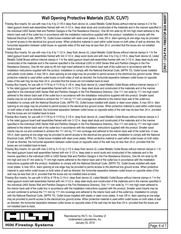
Firestop Box Inserts, for use with max 4 by 4 by 2-1/8 in deep flush device UL Listed Metallic Outlet Boxes without internal clamps in 2 hr fire
rated gypsum board wall assemblies framed with min 3-1/2 in. deep steel studs and constructed of the materials and in the manner specified in
the individual U400 Series Wall and Partition Designs in the Fire Resistance Directory. One 94 mm wide by 95 mm high insert adhered to the
interior back wall of the outlet box in accordance with the installation instructions supplied with the product. Installation to comply with the
National Electrical Code, (NFPA 70). Outlet boxes installed with steel cover plates. A max 3/8 in. diam opening at one edge may be provided
to permit access to the electrical box ground screw. When protective material is used within outlet boxes on both sides of wall as directed, the
horizontal separation between outlet boxes on opposite sides of the wall may be less than 24 in. provided that the boxes are not installed
back-to-back.
Firestop Box Inserts, for use with max 4 by 4 by 1-1/2 in. deep flush device UL Listed Metallic Outlet Boxes without internal clamps in 1 hr fire
rated gypsum board wall assemblies framed with min 3-1/2 in. deep wood studs and with max 4 by 4 by 2-1/8 in. deep flush device UL Listed
Metallic Outlet Boxes without internal clamps in 1 hr fire rated gypsum board wall assemblies framed with min 3-1/2 in. deep steel studs and
constructed of the materials and in the manner specified in the individual U300 or U400 Series Wall and Partition Designs in the Fire
Resistance Directory. One 94 mm wide by 95 mm high insert adhered to the interior back wall of the outlet box in accordance with the
installation instructions supplied with the product. Installation to comply with the National Electrical Code, (NFPA 70). Outlet boxes installed
with plastic cover plates. A max 3/8 in. diam opening at one edge may be provided to permit access to the electrical box ground screw. When
protective material is used within outlet boxes on both sides of wall as directed, the horizontal separation between outlet boxes on opposite
sides of the wall may be less than 24 in. provided that the boxes are not installed back-to-back.
Firestop Box Inserts, for use with 4-11/16 by 4-11/16 by 2-1/8 in. deep flush device UL Listed Metallic Outlet Boxes without internal clamps in 1
hr fire rated gypsum board wall assemblies framed with min 3-1/2 in. deep steel studs and constructed of the materials and in the manner
specified in the individual U400 Series Wall and Partition Designs in the Fire Resistance Directory. One 111 mm wide by 111 mm high insert
adhered to the interior back wall of the outlet box in accordance with the installation instructions supplied with the product. Smaller sized
inserts may be cut and combined to achieve the 111 mm by 111 mm coverage and adhered to the interior back wall of the outlet box.
Installation to comply with the National Electrical Code, (NFPA 70). Outlet boxes installed with plastic or steel cover plates. A max 3/8 in. diam
opening at one edge may be provided to permit access to the electrical box ground screw. When protective material is used within outlet boxes
on both sides of wall as directed, the horizontal separation between outlet boxes on opposite sides of the wall may be less than 24 in. provided
that the boxes are not installed back-to-back.
Firestop Box Inserts, for use with 4-11/16 by 4-11/16 by 2-1/8 in. deep flush device UL Listed Metallic Outlet Boxes without internal clamps in 2
hr fire rated gypsum board wall assemblies framed with min 3-1/2 in. deep steel studs and constructed of the materials and in the manner
specified in the individual U400 Series Wall and Partition Designs in the Fire Resistance Directory. One 111 mm wide by 111 mm high insert
adhered to the interior back wall of the outlet box in accordance with the installation instructions supplied with the product. Smaller sized
inserts may be cut and combined to achieve the 111 mm by 111 mm coverage and adhered to the interior back wall of the outlet box. A max
3/8 in. diam opening at one edge may be provided to permit access to the electrical box ground screw. Installation to comply with the National
Electrical Code, (NFPA 70). Outlet boxes installed with steel cover plates. When protective material is used within outlet boxes on both sides
of wall as directed, the horizontal separation between outlet boxes on opposite sides of the wall may be less than 24 in. provided that the
boxes are not installed back-to-back.
Firestop Box Inserts, for use with max 3-3/4 by 5-1/2 by 2-1/2 in deep flush device UL Listed Metallic Outlet Boxes without internal clamps in 1 hr
fire rated gypsum board wall assemblies framed with min 3-1/2 in. deep steel or wood studs and constructed of the materials and in the
manner specified in the individual U300 or U400 Series Wall and Partition Designs in the Fire Resistance Directory. One 94 mm wide by 95
mm high and one 47 mm wide by 71 mm high inserts adhered to the interior back wall of the outlet box in accordance with the installation
instructions supplied with the product. Installation to comply with the National Electrical Code, (NFPA 70). Outlet boxes installed with steel
cover plates. A max 3/8 in. diam opening at one edge may be provided to permit access to the electrical box ground screw. When protective
material is used within outlet boxes on both sides of wall as directed, the horizontal separation between outlet boxes on opposite sides of the
wall may be less than 24 in. provided that the boxes are not installed back-to-back.
Firestop Box Inserts, for use with 4-3/8 by 4-7/8 by 2-1/4 in. deep flush device UL Listed Metallic Outlet Boxes without internal clamps in 1 hr fire
rated gypsum board wall assemblies framed with min 3-1/2 in. deep steel studs and constructed of the materials and in the manner specified in
the individual U400 Series Wall and Partition Designs in the Fire Resistance Directory. One 111 mm wide by 111 mm high insert adhered to
the interior back wall of the outlet box in accordance with the installation instructions supplied with the product. Smaller sized inserts may be
cut and combined to achieve the 111 mm by 111 mm coverage and adhered to the interior back wall of the outlet box. Installation to comply
with the National Electrical Code, (NFPA 70). Outlet boxes installed with plastic or steel cover plates. A max 3/8 in. diam opening at one edge
may be provided to permit access to the electrical box ground screw. When protective material is used within outlet boxes on both sides of wall
as directed, the horizontal separation between outlet boxes on opposite sides of the wall may be less than 24 in. provided that the boxes are
not installed back-to-back.
Reproduced by HILTI, Inc. Courtesy of
Underwriters Laboratories, Inc.
January 30, 2019
Page: 6 of 7